Showing posts with label Home Automation. Show all posts

Thursday, December 28, 2017

Controlling X10 with Alexa

 I thought it would be fun to control the X10 modules in my house with an Echo Dot .

I am unapologetic about using this 1980's technology for much of my HA.  It's cheap and it works for me.

A quick search revealed that there is an Arduino library written by  Tinkerman that interfaces an ESP8266 to Alexa. (It mimics Belkin WeMo switches.)

Once you have the ESP8266 responding to Alexa, the world is your oyster!

Since I have already written the code to control the CM17A X10 module in Arduino, it was just a matter of combining the two functionalities.

In use, the chain of events is as follows ...
I tell Alexa, "turn tree on". Alexa sees a WeMo switch device named "tree". The Arduino sketch receives that event and calls the corresponding house and unit command for the CM17A. The CM17A transmits the code wirelessly to a TM751 transceiver (or the like) which puts the signal on the powerline. The signal is picked up by an X10 module which turns on the device.

Hardware-wise you need some kind of ESP8266 dev board, an optional I2C OLED display, a CM17A module (AKA X10 Firecracker),  an X10 wireless receiver, a lamp or appliance module. You also need a level shifter.


The level shifter is needed because the ESP8266 is a 3.3V device and the CM17A requires ~5V to operate. Also, since the CM17A is powered by the difference between RTS and DTR,  strong pullup resistors (330Ω) must also be used on the high side of these signals. Here's a rough diagram ...


I have the source code pretty much finalized for this project. If you are interested, you can download what I currently have here,

Enjoy!


Sunday, November 22, 2015

Network Control of X10 - take 2

I posted an earlier version of this, but it was based on the Atmega328 and an Ethernet module.

This version is based on the ESP8266 which provides the microprocessor and connection to the network via WiFi.

I've been having a ball with the ESP8266. It's cheap, programs with the Arduino IDE, and it just works. I've already created a product with it that connects my Geiger Kits to the internet.

So what is it?
The ESP8266 puts up a webpage (like the above) on your local network. The page has buttons for the X10 devices that you want to control. When a button is pressed the ESP8266 drives a CM17A and turns your device on or off. The page also displays any sensor readings that are connected to the ESP8266. So if you are into X10 home automation, this is a cool gadget.

Hardware-wise it's an ESP12 variant of the ESP8266. It's connected to the CM17A through a level shifter. The level shifter is needed because the ESP8266 is a 3.3V device and the CM17A requires 5V to operate. (Since the CM17A is powered by the difference between RTS and DTR strong pullup resistors must be used on the high side - 330Ω.)


You can also attach an I2C OLED display to the ESP8266 which will show the X10 commands that were received.


Here is the complete setup. I used the ESP8266 development board I created for the GK-WiFi kit (available here).


The software is finished (as far as I'm concerned) and is available here.

Saturday, January 24, 2015

Network Control of X10

I really love remote control!
This project allows you to control your X10 devices from any web browser.

The Arduino is used as a web server which puts up a page with controls for House Code, Unit Code, and Command. 

The response is sent back to the Arduino which sends out the X10 commands wirelessly through the CM17A module.

So far it's just on my local network but it appears to be working pretty well.

Still a few things I'd like to change, but the current  Arduino source code is available here.

Saturday, January 22, 2011

X10 Remote Temperature - Redo

I became interested in the ATtiny85 processor recently. Up till now, my projects were based on the ATmega328 or the ATmega644. The  ATtiny85 is just that, tiny - only 8 pins vs. 28 on the ATmega328. The photo on the left shows the new  X10 temperature transmitter, with the DS1621 temperature chip on the left and the ATtiny85 on the right.
(The CM17A X10 RF transmitter is not shown.)

This board replaces what I had in the original X10 Wireless Temperature Transmitter which I've been using for the past year and a half.  (post is here)

So why the redo? The rational part of the answer is that I wanted the batteries to last longer.

The original temperature transmitter drew a whopping 2.2mA while in sleep mode. It was powered by 2 NiMH AA batts stepped up to 5V with a boost inverter. I'd change the batteries every month or so.

The redo board draws about .07mA while in sleep mode. It's running directly on 4 NiMH AA batts.  I'm guessing I'll change the batteries every 1.5 years or so. I choose AA batts over a 3.7V LiPo because it's easier to replace the NiMH batts with fresh ones, and I wanted the higher voltage for better range on the X10 transmitter. However, it's worth noting that the processor draws less current at lower voltages.

Most of the power savings can not be attributed to using the ATtiny, however. Along the way, I discovered a few things.

The first had to do with how I was reading the temperature on the DS1621. I was using "continuous mode" (most examples use this mode) which would give me a reading as soon as I asked for it, but at the cost of almost 1mA! I switched to "one-shot" mode which makes me wait ~750ms for a reading, but at a huge savings.

The second thing I found is that the CM17A library I made left the RTS & DTR lines high after transmitting. Setting them low, results in about a .5mA savings. Note that if you are using this lib and want to try it, be sure to give a nice delay before transmitting after you set the lines high. (There's always a trade off!)

I always use sleep mode for the lowest power usage when not transmitting. It's set to transmit about once every 6 minutes. There are several sleep mode routines for the ATmega processors, but the ATtiny needs entirely different registers set. I found good info on sleep mode, and good tutorials for the ATtiny at brownsofa.org and Inside Gadgets.

The way to do the things mentioned above will be much clearer when you look at the the example code, which will be provided later in this post. But now, I would like to describe how to go about using the Arduino environment to work with the ATtiny85 chip, and most of all, how to get I2C working on them so you can communicate with the DS1621, real time clocks, and even 2x16 displays - all with an 8 pin chip!

The first thing you must do is to get the ATtiny "core files" for the Arduino environment. There are several out there - each supporting more or less of the standard Arduino features. Core files, and instructions on how to get started with the Tiny85 can be found here, however, I prefer the core files from here.

You can use the ArduinoISP as a way of downloading the sketch into the ATtiny. I've used it and it works fine - just be sure to disable the automatic reboot after load! For me, an easy way to do that is to use a serial cable instead of the USB cable. However, there are other ways to do it. Keep in mind, you only need to hit reset when you load the ArduinoISP on to your Arduino. Once it's an ISP, change the Board type to ATTiny85, and just hit "Upload" (don't press "reset"). After you work with the ArduinoISP a while, I think you will want a real ISP Programmer to load the ATtiny. They are cheap and much easier!

Finally, get at least the TinyWireM "master" library for this project. I made a Playground article that explains this library and has a link to download it. The Playground article is here.

OK, almost done. To get the source code for the new X10 Remote Temperature Transmitter, you can download it here. (a new version as of 3/13/11)

 [1/18/15] You can get a schematic for this project here.

Saturday, October 16, 2010

Receiving X10 RF Transmissions (Updated 11/21/10)

For me, at least, this was the last piece of the open hardware X10 puzzle. In this blog you'll find open hardware projects that receive and transmit PLC (powerline) signals, as well as transmitting X10 RF signals (via the CM17A). Now sitting in front of me, is an off the shelf 315MHz receiver (detuned to 310Mhz), happily beeping away each time a warm body crosses an X10 motion detector.

The receiver is from Sparkfun, but any similar receiver should work. The key is to get one with a tuning slug as opposed to a crystal. The software that interfaces the receiver to the Arduino is from a suite of X10 libraries written by ThomasM. You can find the whole suite (PLC transmit & receive, RF receive, and IR receive) here. Having written an earlier version of PLC receive, I'd recommend his version for PLC receive and transmit as well.

So lets get started. Get a  315MHz receiver, wire it up per the data sheet, get Thomas's libraries and his example sketch, (or get the "test & calibrate" sketch I made here). Press a key on an X10 RF remote. It should work right away, but only at close range.

So the next step is to tune this receiver closer to 310MHz. You'll want to start by adding an antenna. This page gave me the following lengths (in inches) for a vertical wire antenna at 310MHz:

  • 1/4 wave - 9 1/16"
  • 1/2 wave - 18 1/8"
  • full wave - 36 1/4"
I started with 1/4 wave whip antenna, but the ultimate may be the "egg beater" antenna (Google for examples).

Now it's time to tune the receiver to 310Mhz. I don't have a scope, and I found that a sound card scope was of little help, since the signal is clipped to soundcard inputs, so I came up with two alternate methods.

The first method I tried was to simply connect the output (data pin) of the receiver to the Aux-in on my PC. You will hear a lot of noise! (This is due to the AGC built into the receiver.) However you will clearly hear the RF signal when you push a button on an X10 RF remote - as long as it's close and pointing at the antenna. Pointing the remote away from the antenna gave a fainter signal, and moving it further away made it even fainter. So with the faint signal, I simply turned the tuning slug until I got a clearer sound in the speakers when I pushed a button on the remote. Not very scientific, but it seemed to do the job. (I started by turning the slug CCW - this post said ~160° CCW.)

Later I used a different method which seemed to be more "real word". I made the "test & calibrate sketch" linked above. It simply beeps a piezo and outputs to serial whenever the receiver has a good read. Then I clamped a button down on an X10 RF Remote (HR12A) so it would continuously transmit,  and located it at varying distances from the receiver. While listening for the beeps, I adjusted the tuning slug for good reads at the furthest distance.

While using the second method, I also played around with antennas.  The 1/4 wave whip antenna really didn't seem to do much, and I couldn't pick up signals if the transmitter was outside my house. Then I tried a 36 1/4"  piece of twisted pair from a phone cable. One wire to the ANT pin on the receiver and the other to GND. This made a big difference, and the grounded lead contributed to the difference.

That's about where I am at this point. Interfaced to the example sketch I can receive RF signals from the motion sensors on my front and back doors. There's more about this in last half of this thread in the Arduino forum. [4-3-13] (There were changes to X10rf.h - here is the modified version I used.)

Not sure at this point where I want to go with this - perhaps a "whole house" X10 receiver with some other goodies, or some little dedicated device. We'll see.

Monday, October 19, 2009

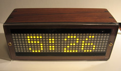
Building a Case for the Nex10

Sounds like something a lawyer would say.

Building this case took a solid weekend.

The wood is walnut. I know this wood well because 25 years ago it was a tree on our land in Arkansas. We had to cut down some walnuts to make room for the house and we hauled them to the mill and had them cut into boards. For me, it's a nice mix of the past and present.

I planned a board down to 5/16", cut it up, and mitered the ends. Then I glued up a box.

The board was wide enough to make 2 boxes. I also made the acrylic front using acetone to chemically wield two black strips that hold the 8x32 matrix in place. The IR sensor is glued over a small hole drilled in the top black strip.

I got a few gaps in the wield which show up as shinny spots on the black strips. Next time a little more acetone and better clamping. I used tripoli abrasive on a buffing wheel to finish the edges.

To make the box stronger, and more interesting, I added ebony splines in the corners. I do this with a jig I made for my router table. Its kind of a sled that holds the box at 45° (photo).

After cutting off the excess ebony (photo), I rounded all the corners with the router.

On the inside of the box there's a platform that holds the board in position to line up the SD socket with a slot in the side of the case (photo). I used the router to cut the slot, and a little sanding drum to make the recess in the case for fingers to get at the card (photo).

A back cover of clear acrylic was made to fit into a rabbet cut around the back of the box. A power jack and an RJ14 jack for the PSC05 was added to the back. There's also a hole for the USB cable when I'm developing (photo). (Later I added a wood dowel with a hole that fits over the stem of the reset button to bring it out to the back of the case (photo).

The box was finished with a light coat of tung oil varnish. (photo)

Finally, the obligatory video . . .


Friday, October 16, 2009

Nex10 Functionality

Almost all of the functionality of the "X10 Book" is included in this project and new features have been added.

What's missing is the ability to drive relays and LED's. My thinking is to include such things as optional "add-ons". So a "relay pack" could be designed for lawn sprinklers. I'm currently working on a phone dialer (see above), and I'm considering other ad-on modules like a Bluetooth PC interface. But I've gotten ahead of myself.

One of the biggest advantages over the X10 Book is the ability to read in configuration files that are put on the SD card. So far there are 4:
  1. TIMEDATE.TXT - enter the time and date on a single line, put the card in the Nex10, restart, and the time and date are set. (Then the file is deleted from the card.)
  2. SETUP.TXT - this file is loaded into the external EEPROM and deleted after loading. It has several sections where you can define;
    Messages - like names of the weekdays, full moon names, etc.
    Reminders - yearly reminders like birthdays, scheduled salary reviews, etc.
    X10 Events - timers to send X10 commands at certain times.
    X10 Profiles - Friendly names for House / Unit codes so instead of "A-5" "Desk Lamp" is displayed. Other parameters in each Profile control beep type, display and logging options.
    X10 Macros - (work in progress) "IF A-5 ON - Send G-2 and G-3 OFF" is a simple example. They should be pretty powerful - stay tuned.
  3. PARAMS.TXT - This file contains user defined parameters such as the date and time format, the house code for the remote temp sensor, high / low temp alarms, various delay times, etc.I've pretty much replaced all "hard coded" settings with these parameters.
  4. FONTS.TXT - Since we're using an LED display, a set of fonts must be defined. All characters from ASCII 32 to 127 are included. Additionally about 20 or so "sprites" like the moon phases are defined. This file is loaded to the ATmega644P EEPROM instead of the external EEPROM. It is deleted after it is read in.
So what's it do? We'll you should have some idea from the above, but here's the list in all it's gory detail . . .

Clock Features:
  • Time - set by writing it to a file on the SD card, automatically adjusts for DST. The clock has a battery backup.
  • Day of the week is displayed with a user defined message for each day.
  • The current phase of the moon is displayed as an animated sprite. The number of days to the next full moon, and name of the full moon, is displayed as a scrolling message.
  • The times for sunrise and sunset are displayed.
  • Yearly reminders will display a day in advance and on the day.
X10 Features:
  • All X10 signals that come across the powerline are displayed and optionally logged. If a "profile" was set up for the house and unit code, a friendly name will display - i.e. "Desk Lamp". The profile also has options for 3 levels of "beep", no display, and no logging.
  • Logs are written to the SD card as a text file readable by a PC. A new log file is automatically created each month.
  • The current status of all 255 devices is kept. The status table can be written to the SD card or cleared using the TV remote. The table will be used for one type of "macro" command.
  • A TV remote may be used to manually send X10 commands.
  • X10 commands can be set up to be automatically sent at certain times during the day.
  • X10 Macros are defined in a section of the setup file. Current types supported are; "if cmnd-then cmnds" (up to 5 thens), "if cmnd and time > x or < y then cmnd, if cmnd - display time, temp, etc. I am working on more types like "if temperature".
  • Nex10 will receive the temperature from a remote wireless sensor on a dedicated House Code. (See this.) The time and temperature is logged to a separate file on the SD card. The current temperature and the low and high temperature for the day is displayed in the display loop.
  • Alarms may be set to provide an audible warning if, for example, the the garage door has not closed in a certain time.
  • There's a good chance I forgot something.
Most of the time, the device is just listening for X10 commands coming from the PSC05. Once every 5 minutes or so, it goes into it's display routine and shows all the things listed above under clock features. The display routine can also be activated via the remote, or from a macro.

Credit and thanks to Bill Westfield, Andrew Hedges, and Bill Ho for the ht1632 code that writes to the Sure matrix, Bill Greiman for the fantastic SD card library fat16lib, B. Hagman for a slick non-blocking Tone library, and Mike Rice for a great little sunrise / sunset time calc. library.

Thursday, September 17, 2009

Is the Garage Door Closed?


After the second time my neighbor had to tell me that I left my garage door open, I thought I'd throw a little technology at my senility.


I could have gone the route of using a PSC01 "PowerFlash" but I had a few problems with that:

  • It requires a "normally closed" reed switch (which opens when the door is closed and next to the magnet. 
  • It only sends the X10 command one time. 
  • It would plug into the same outlet as the door opener - not a good time or place to send X10 signals on the power line. 
  • I wanted to make my own. :-) 
So this ugly little board above was my solution. It consists of an ATmega168 (running on it's internal oscillator), and a CM17A "Firecracker" (removed from it's jacket). It's wire-tied to it's wall wart.

When the normally open reed switch closes - because the door is open - it causes a pin based interrupt in the ATmega168. The CM17A then sends a preset House + Unit + ON wirelessly to a TM751 receiver and it's put on the power line and picked up by the X10 Book (see below). The command is sent 3 times with a delay in between to make sure the signal gets through. When the door closes, an OFF signal is sent 3 times.

(get Arduino sketch)

On the X10 Book side, a timer is started when the first door open signal arrives. After a preset time, the X10 Book beeps every few seconds until it receives a door closed signal.

If the door is open late at night, the X10 Book will also turn on lights near the garage. (I could have it wake me up, but I'd be too tired and too scared to want that!)

Friday, May 22, 2009

X10 Wireless Temperature Transmitter


This is a battery operated Arduino project that uses the CM17A to wirelessly transmit the temperature to the power line. From there, it is picked up by the X10 Book, (see below) and displayed and logged. (It can also be used to trigger macros.)

The PSC05/TW523 will not receive X10 "extended" codes. Therefore I had to get tricky with how I sent the temperature and how I received it. This means that the technique requires you to have control over the receiving end as well.

The idea is simple. An entire House Code is dedicated to the temperature. Each digit is sent as a Unit Code representing that digit (i.e. Unit Code"3" is sent if the digit is 3). The Command is used to indicate the digit position. So for the least significant digit, I used "OFF" for the next digit I used "ON". BRIGHT and DIM can also be used for more positions or to represent + and -. So with 4 types of commands (and 4 separate transmissions) you can transmit variables up to "9999" or "+/-999".

[detail . . .]
Since Unit Codes really have a range of 1-16 you could use this to transmit even larger values - with 2 transmissions you could transmit and digit up to 255. However I choose not to do this because the CM17A is transmitting to the same (TM751) receiver that I use to receive form a motion sensor. The motion sensor uses Unit Codes 1 and 2. So in actuality I offset the digits by 5, leaving the first 5 Unit Codes. (Two for the motion sensor and 3 reserved.) I'm sure there are other methods you can use to transmit values, but this works fine for me.

So much for theory!
Since the CM17A is wireless, it's a nice idea to make the whole thing battery operated. There are techniques to use with the Arduino to conserve battery power. I used one that combines "sleep" mode with the "watchdog timer" There is a good example of this here. The idea is to have the Arduino in low power sleep mode, wake it up every now and then, and have it read and transmit the temperature before going back to sleep. The example cited has a maximum sleep time only 8 seconds, but on waking, a variable can simply be incremented and skip sending until say 10 wakeups have occurred. Mine sends the temperature about every 2 min. (The less often you send, the longer your battery lasts.)

I used the DS1621 temperature sensor. It's I2C and simple to connect. You will find examples of how to use it on the Arduino Forum.
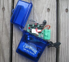
I put everything in a waterproof box. A word about the picture. You can see the DS1621 temperature sensor on the "spring" ribbon cable. The green square on the right is the CM17A with it's jackets removed and covered with heat shrink tubing. The Arduino (ATmemg128) board is a custom board I made that includes a boost circuit so it only needs 2 AA batteries. You can use any Arduino and use 3 AA batteries instead.

On the temperature receiver side (the X10 Book in my case) I look for commands from the dedicated temperature House Code. When I get one, I determine which digit position it represents by the command code, convert the Unit Code into a digit, and store it in a global for that digit position. It's OK if a digit is somehow missed, it's likely to be picked up from the next transmission. When I want to log or display the temperature (periodically or using the TV Remote) I simply multiply the values in the various digit positions to get the current temperature.

Here's a short video . . .

Thursday, May 21, 2009

Sending and Receiving with the PSC05 / TW523


For a long time, the Arduino community had a library (written by Tom Igoe) that would interface the Arduino to the PSC05/TW523 so that it could send X10 commands. (available here) Since I was already wirelessly sending commands via the CM17A, I never took much interest in it.

But then I thought if you could also receive commands with the PSC05/TW523, you could pretty much make your own X10 controller and replace the ActiveHome SW and the CM11A/CM15A hardware.

Again the web provided a lot of the great detail on the protocol that enabled me to write an Arduino driver to receive commands with the PSC05/TW523. I created an example sketch and wrote a lot of background and posted it on the Arduino Playground here. Since the receive driver can coexist with the send library, the Arduino now has a complete interface with the PSC05/TW523 that allows you to send and receive X10 commands.


[3/30/2010] Thanks to Creatrope, a beta of the combined X10 send / receive library is now available - you'll find it here. [1/5/11] Creatrope site down. You can use the separate X10 transmit & receice libs or check out ThomasM's library here

The Playground article should tell you all you need to know about how to use this software, so I won't go into it here. Just to say that the Arduino is always looking for any X10 signal on the powerline at every zero crossing of the AC. When it gets one, it sets a flag, and fills out globals for the House Code, Unit Code, and Command that are used by your program.

With this complete, I was able to make my own X10 controller called the "X10 Book" that I will write about in my next post. 


Edit Nov. 2, 09: Based on a comment by Phil, here's a link to an Ap Note from Microchip that describes how to use a PIC to essentially replace the PSC05. It would be great to port it to ATmega chips. Thanks Phil!


Edit Feb. 23, 09: I've received some very good feedback from Johannes related to changing the send and receive software to have reliable communications using 50Hz line frequency. (He uses an "XM10" X10 module instead of the PSC05 / TW523 for 220V 50Hz.) It's simply a matter of changing 4 #defines - 2 in the X10.lib (for sending) and 2 in my code (for receiving).


In the source for your X10.lib, in X10constants.h change:
#define BIT_DELAY from 1778 to 2133
#define BIT_LENGTH from 800 to 900


In my example for the X10 Receive function, in PSC05.h change:
#define OFFSET_DELAY from 500 to 800
#define HALF_CYCLE_DELAY from 8334 to 10000


Thanks Johannes! I'm sure others will find this helpful.

Wednesday, May 20, 2009

The CM17A and Arduino

My first X10 project was to create an interface between the Arduino and the CM17A (aka "Firecracker"). The CM17A is a dongle that wirelessly (RF) sends X10 commands to X10 RF receivers. The receivers then send signals down the house wiring to control lights and appliances.

After many hours of Googling, I could not find any examples of an interface other than some written in assembler. However, I did find lots of good information about the protocol that is used to talk to the CM17A. With that I was able to write a small program ("sketch") that demonstrates how to have the Arduino talk to the CM17A. I wrote up an article with the explanation and example and posted it on the Arduino Playground here. It should tell you all you need to know.
I made a short video of a simple example where a TV remote is used to have the CM17A send X10 commands to a light.


Don't let the custom boards and led matrix scare you. There are much simpler ways to use the CM17A with Arduino. In a future post I will describe how it can be used to send the temperature to a home made X10 Controller.

What is Arduino? / What is X10?

It's likely that most people reading this will know a lot about either Arduino or X10. (If you know about both - you're in good shape. If you don't know about either - I'm surprised you're here!) In any case, I won't go into detail about either. You can learn about Arduino here, and Google will give you lots of info on X10.

In short, the Arduino is an inexpensive (~$30) microcomputer that you program in C/C++ that has input and output pins that connect to real world devices. I choose the Arduino because of it's popularity, price and wonderful support.  It's likely another type of microcomputer can be used for these projects, but I'm only comfortable discussing the Arduino and the C language.

X10 is a home automation system that typically sends signals down your power line to remotely control lights and appliances. There are many types of modules one can get to do various things. While X10 is old technology, it still has some key advantages regarding remote control. Primarily, it is the cheapest and safest way I know of to control things that plug into the power line. 

So what are the advantages when you combine the Arduino and X10? Here is a diagram where I tried to show X10 and Arduino working together.


From an X10 user's perspective, the X10 world now becomes your oyster. You are no longer bound by a PC and the limited functionality and cost of commercial software. You can create entirely new functionality while replacing your ActiveHome SW and your CM11A / CM15A interface device.

From an Arduino user's perspective, you gain an option for wireless remote control at a much lower cost per controlled device than say XBee and roll your own triacs. It's also a hell of a lot safer than mucking around with line voltage. The modules are UL approved and cost as little as $6 on Ebay  (link just an example).

Obviously, all of the above is just my opinion and points can be argued. You can fault X10 for not being reliable. Personally I solved most of my issues with a XPCR coupler /filter / amplifier. For those in 220V land, X10 charges an arm and a leg extra for the 200V models. See this website for a cheap way to convert most 115V modules.

OK, enough background.