Showing posts with label CM17A. Show all posts

Thursday, December 28, 2017

Controlling X10 with Alexa

 I thought it would be fun to control the X10 modules in my house with an Echo Dot .

I am unapologetic about using this 1980's technology for much of my HA.  It's cheap and it works for me.

A quick search revealed that there is an Arduino library written by  Tinkerman that interfaces an ESP8266 to Alexa. (It mimics Belkin WeMo switches.)

Once you have the ESP8266 responding to Alexa, the world is your oyster!

Since I have already written the code to control the CM17A X10 module in Arduino, it was just a matter of combining the two functionalities.

In use, the chain of events is as follows ...
I tell Alexa, "turn tree on". Alexa sees a WeMo switch device named "tree". The Arduino sketch receives that event and calls the corresponding house and unit command for the CM17A. The CM17A transmits the code wirelessly to a TM751 transceiver (or the like) which puts the signal on the powerline. The signal is picked up by an X10 module which turns on the device.

Hardware-wise you need some kind of ESP8266 dev board, an optional I2C OLED display, a CM17A module (AKA X10 Firecracker),  an X10 wireless receiver, a lamp or appliance module. You also need a level shifter.


The level shifter is needed because the ESP8266 is a 3.3V device and the CM17A requires ~5V to operate. Also, since the CM17A is powered by the difference between RTS and DTR,  strong pullup resistors (330Ω) must also be used on the high side of these signals. Here's a rough diagram ...


I have the source code pretty much finalized for this project. If you are interested, you can download what I currently have here,

Enjoy!


Sunday, November 22, 2015

Network Control of X10 - take 2

I posted an earlier version of this, but it was based on the Atmega328 and an Ethernet module.

This version is based on the ESP8266 which provides the microprocessor and connection to the network via WiFi.

I've been having a ball with the ESP8266. It's cheap, programs with the Arduino IDE, and it just works. I've already created a product with it that connects my Geiger Kits to the internet.

So what is it?
The ESP8266 puts up a webpage (like the above) on your local network. The page has buttons for the X10 devices that you want to control. When a button is pressed the ESP8266 drives a CM17A and turns your device on or off. The page also displays any sensor readings that are connected to the ESP8266. So if you are into X10 home automation, this is a cool gadget.

Hardware-wise it's an ESP12 variant of the ESP8266. It's connected to the CM17A through a level shifter. The level shifter is needed because the ESP8266 is a 3.3V device and the CM17A requires 5V to operate. (Since the CM17A is powered by the difference between RTS and DTR strong pullup resistors must be used on the high side - 330Ω.)


You can also attach an I2C OLED display to the ESP8266 which will show the X10 commands that were received.


Here is the complete setup. I used the ESP8266 development board I created for the GK-WiFi kit (available here).


The software is finished (as far as I'm concerned) and is available here.

Saturday, January 24, 2015

Network Control of X10

I really love remote control!
This project allows you to control your X10 devices from any web browser.

The Arduino is used as a web server which puts up a page with controls for House Code, Unit Code, and Command. 

The response is sent back to the Arduino which sends out the X10 commands wirelessly through the CM17A module.

So far it's just on my local network but it appears to be working pretty well.

Still a few things I'd like to change, but the current  Arduino source code is available here.

Saturday, January 22, 2011

X10 Remote Temperature - Redo

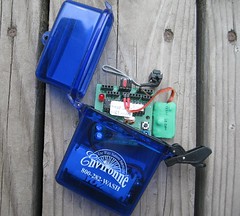
I became interested in the ATtiny85 processor recently. Up till now, my projects were based on the ATmega328 or the ATmega644. The  ATtiny85 is just that, tiny - only 8 pins vs. 28 on the ATmega328. The photo on the left shows the new  X10 temperature transmitter, with the DS1621 temperature chip on the left and the ATtiny85 on the right.
(The CM17A X10 RF transmitter is not shown.)

This board replaces what I had in the original X10 Wireless Temperature Transmitter which I've been using for the past year and a half.  (post is here)

So why the redo? The rational part of the answer is that I wanted the batteries to last longer.

The original temperature transmitter drew a whopping 2.2mA while in sleep mode. It was powered by 2 NiMH AA batts stepped up to 5V with a boost inverter. I'd change the batteries every month or so.

The redo board draws about .07mA while in sleep mode. It's running directly on 4 NiMH AA batts.  I'm guessing I'll change the batteries every 1.5 years or so. I choose AA batts over a 3.7V LiPo because it's easier to replace the NiMH batts with fresh ones, and I wanted the higher voltage for better range on the X10 transmitter. However, it's worth noting that the processor draws less current at lower voltages.

Most of the power savings can not be attributed to using the ATtiny, however. Along the way, I discovered a few things.

The first had to do with how I was reading the temperature on the DS1621. I was using "continuous mode" (most examples use this mode) which would give me a reading as soon as I asked for it, but at the cost of almost 1mA! I switched to "one-shot" mode which makes me wait ~750ms for a reading, but at a huge savings.

The second thing I found is that the CM17A library I made left the RTS & DTR lines high after transmitting. Setting them low, results in about a .5mA savings. Note that if you are using this lib and want to try it, be sure to give a nice delay before transmitting after you set the lines high. (There's always a trade off!)

I always use sleep mode for the lowest power usage when not transmitting. It's set to transmit about once every 6 minutes. There are several sleep mode routines for the ATmega processors, but the ATtiny needs entirely different registers set. I found good info on sleep mode, and good tutorials for the ATtiny at brownsofa.org and Inside Gadgets.

The way to do the things mentioned above will be much clearer when you look at the the example code, which will be provided later in this post. But now, I would like to describe how to go about using the Arduino environment to work with the ATtiny85 chip, and most of all, how to get I2C working on them so you can communicate with the DS1621, real time clocks, and even 2x16 displays - all with an 8 pin chip!

The first thing you must do is to get the ATtiny "core files" for the Arduino environment. There are several out there - each supporting more or less of the standard Arduino features. Core files, and instructions on how to get started with the Tiny85 can be found here, however, I prefer the core files from here.

You can use the ArduinoISP as a way of downloading the sketch into the ATtiny. I've used it and it works fine - just be sure to disable the automatic reboot after load! For me, an easy way to do that is to use a serial cable instead of the USB cable. However, there are other ways to do it. Keep in mind, you only need to hit reset when you load the ArduinoISP on to your Arduino. Once it's an ISP, change the Board type to ATTiny85, and just hit "Upload" (don't press "reset"). After you work with the ArduinoISP a while, I think you will want a real ISP Programmer to load the ATtiny. They are cheap and much easier!

Finally, get at least the TinyWireM "master" library for this project. I made a Playground article that explains this library and has a link to download it. The Playground article is here.

OK, almost done. To get the source code for the new X10 Remote Temperature Transmitter, you can download it here. (a new version as of 3/13/11)

 [1/18/15] You can get a schematic for this project here.

Thursday, September 17, 2009

Is the Garage Door Closed?


After the second time my neighbor had to tell me that I left my garage door open, I thought I'd throw a little technology at my senility.


I could have gone the route of using a PSC01 "PowerFlash" but I had a few problems with that:

  • It requires a "normally closed" reed switch (which opens when the door is closed and next to the magnet. 
  • It only sends the X10 command one time. 
  • It would plug into the same outlet as the door opener - not a good time or place to send X10 signals on the power line. 
  • I wanted to make my own. :-) 
So this ugly little board above was my solution. It consists of an ATmega168 (running on it's internal oscillator), and a CM17A "Firecracker" (removed from it's jacket). It's wire-tied to it's wall wart.

When the normally open reed switch closes - because the door is open - it causes a pin based interrupt in the ATmega168. The CM17A then sends a preset House + Unit + ON wirelessly to a TM751 receiver and it's put on the power line and picked up by the X10 Book (see below). The command is sent 3 times with a delay in between to make sure the signal gets through. When the door closes, an OFF signal is sent 3 times.

(get Arduino sketch)

On the X10 Book side, a timer is started when the first door open signal arrives. After a preset time, the X10 Book beeps every few seconds until it receives a door closed signal.

If the door is open late at night, the X10 Book will also turn on lights near the garage. (I could have it wake me up, but I'd be too tired and too scared to want that!)

Friday, May 22, 2009

X10 Wireless Temperature Transmitter


This is a battery operated Arduino project that uses the CM17A to wirelessly transmit the temperature to the power line. From there, it is picked up by the X10 Book, (see below) and displayed and logged. (It can also be used to trigger macros.)

The PSC05/TW523 will not receive X10 "extended" codes. Therefore I had to get tricky with how I sent the temperature and how I received it. This means that the technique requires you to have control over the receiving end as well.

The idea is simple. An entire House Code is dedicated to the temperature. Each digit is sent as a Unit Code representing that digit (i.e. Unit Code"3" is sent if the digit is 3). The Command is used to indicate the digit position. So for the least significant digit, I used "OFF" for the next digit I used "ON". BRIGHT and DIM can also be used for more positions or to represent + and -. So with 4 types of commands (and 4 separate transmissions) you can transmit variables up to "9999" or "+/-999".

[detail . . .]
Since Unit Codes really have a range of 1-16 you could use this to transmit even larger values - with 2 transmissions you could transmit and digit up to 255. However I choose not to do this because the CM17A is transmitting to the same (TM751) receiver that I use to receive form a motion sensor. The motion sensor uses Unit Codes 1 and 2. So in actuality I offset the digits by 5, leaving the first 5 Unit Codes. (Two for the motion sensor and 3 reserved.) I'm sure there are other methods you can use to transmit values, but this works fine for me.

So much for theory!
Since the CM17A is wireless, it's a nice idea to make the whole thing battery operated. There are techniques to use with the Arduino to conserve battery power. I used one that combines "sleep" mode with the "watchdog timer" There is a good example of this here. The idea is to have the Arduino in low power sleep mode, wake it up every now and then, and have it read and transmit the temperature before going back to sleep. The example cited has a maximum sleep time only 8 seconds, but on waking, a variable can simply be incremented and skip sending until say 10 wakeups have occurred. Mine sends the temperature about every 2 min. (The less often you send, the longer your battery lasts.)

I used the DS1621 temperature sensor. It's I2C and simple to connect. You will find examples of how to use it on the Arduino Forum.
I put everything in a waterproof box. A word about the picture. You can see the DS1621 temperature sensor on the "spring" ribbon cable. The green square on the right is the CM17A with it's jackets removed and covered with heat shrink tubing. The Arduino (ATmemg128) board is a custom board I made that includes a boost circuit so it only needs 2 AA batteries. You can use any Arduino and use 3 AA batteries instead.

On the temperature receiver side (the X10 Book in my case) I look for commands from the dedicated temperature House Code. When I get one, I determine which digit position it represents by the command code, convert the Unit Code into a digit, and store it in a global for that digit position. It's OK if a digit is somehow missed, it's likely to be picked up from the next transmission. When I want to log or display the temperature (periodically or using the TV Remote) I simply multiply the values in the various digit positions to get the current temperature.

Here's a short video . . .

Wednesday, May 20, 2009

The CM17A and Arduino

My first X10 project was to create an interface between the Arduino and the CM17A (aka "Firecracker"). The CM17A is a dongle that wirelessly (RF) sends X10 commands to X10 RF receivers. The receivers then send signals down the house wiring to control lights and appliances.

After many hours of Googling, I could not find any examples of an interface other than some written in assembler. However, I did find lots of good information about the protocol that is used to talk to the CM17A. With that I was able to write a small program ("sketch") that demonstrates how to have the Arduino talk to the CM17A. I wrote up an article with the explanation and example and posted it on the Arduino Playground here. It should tell you all you need to know.
I made a short video of a simple example where a TV remote is used to have the CM17A send X10 commands to a light.


Don't let the custom boards and led matrix scare you. There are much simpler ways to use the CM17A with Arduino. In a future post I will describe how it can be used to send the temperature to a home made X10 Controller.