The basic idea was to allow the MCU to make calls by transmitting DTMF tones, and to receive and decode DTMF tones (keystrokes) made on the phone that was called.
There are other possibilities however. Using the complete interface, it should be possible for the MCU to answer calls, and to transmit "room sounds" picked up by a microphone to the other phone.
If you're only interested in sending and receiving DTMF tones and not interfacing to a phone line, you can skip the next dozen or so paragraphs. The schematics and code samples will still apply.
It all begins with the interface to the actual telephone line. Unfortunately this is trickiest part!
There are two reasons for this:
- Phone lines require a 600 Ohm "balanced line". You can't just slap any old circuit between your "TIP" and "Ring".
- It's illegal!
Lets start with #2. Here I'm speaking from a US and Canadian perspective, but I'm sure it's similar in many countries. In the US, it's FCC Part 68 that makes it illegal to connect any unapproved device across your phone lines. So what can they do? Well, I'm sure it's much worse than tearing off that tag on your mattress. I've read that if you create a problem that must be investigated by the phone company, and it's due to a little circuit you whipped together - your financially liable to cover the cost of the phone companies time. And it's relatively easy to do horrible things to your phone line during the process of creating an interface, and that leads to point #1.
When you Google "phone interface" you'll be drinking from a fire hose of circuits, methods, and projects. I spent a lot of time researching them, and did indeed come up with an interface that "worked". However, what I ended up with, struck me as being sensitive to component values, and somewhat "fragile". By this I mean, for example, that the correct "polarity" for TIP and RING was required. Given that the line should be "balanced" I felt like I disturbed the balance of the force. In short, after all of my experience with electronics, I felt like I was over my head with the interface I came up with. Ironic considering you're dealing with a system that has been around for so long.
For those who want to ignore points 1 & 2 above, here are some of the best resources I found, as well as the schematic for the "working" interface I was using. Big disclaimer here! I do not recommend building your own unapproved interface. Furthermore, I am not responsible for anything you do with any information I am providing. Everything here you use at your own risk.
Some of the telephone interface links I found helpful are:
Just looking at the variety of this information should give you an idea what your up against when rolling your own POTS interface. The interface that I tried is here.
Not a very encouraging beginning is it?
Enter the "Direct Access Arrangement" DAA. This little module is an FCC Part 68 approved interface. Does it make everything OK? I don't think so - it really just makes it a lot easier for you to get your device FCC approved. Will it give you peace of mind? You bet. After switching to a DAA, the TIP and RING polarity did not matter, and everything seems to be much more solid - calls go through 100% of the time. The DAA also saves you from buying an isolation transformer, relay, transistor, and a large capacitor.
The problem is getting your hands on one without having to special order 54 of them from Mouser, etc. After a lot of searching, the best deal I found, for my use, was for a Cermetek CH1817-LM (discontinued) still some left on eBay - here. It will cost you $15-$18 shipped.
Note: If your interested in capturing caller ID, I don't think this is the DAA for you. However, while searching I did see some that will output CID. I also ran across the Holtek HT9032C which looks like an interesting CID chip, but they seem to be hard to find.
Sorry if the above was long and detailed. I wrote it in the interest of saving you a lot of time. However, as always, YMMV.
Once connected to the phone line, I wanted to do several things:
- Have the Nex10 dial my cell when an event ("macro") was triggered.
- Leave a message - a series of beeps.
- Optionally be able to listen in on the room noise from the called phone. (work in progress)
- Capture any key presses I made from my cell. (Not sure how I want to use this yet.)
Note that currently all the communication is initiated by the Nex10. In fact, it is possible to use the RI (ring indicator) on the DAA to answer calls with the Nex10. (No plans yet for this.)
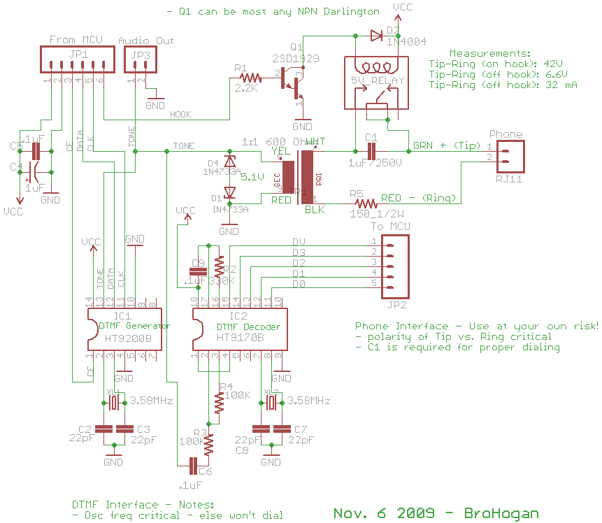
To do the things above, I used 2 chips from Holtek - an HT9200B DTMF generator to dial the call, and a HT9170B DTMF receiver to read the key presses once connected. Both are less than 70¢ each at Futurlec.
I wired both chips per the datasheets and ran the HT9240B in serial mode. Here is my schematic and an Arduino example sketch for the project at that point.
I could have stopped there, but even with serial mode, the interface to the MCU required 8 pins + power. I also want the Nex10 to accept "plug-in modules" - so an I2C interface seemed like the way to go.
I picked the PCF8574 I2C GPIO chip to go between the MCU and the DTMF chips. It's also available at Futurlec and is also wired per the datasheet. (Note: the PCA8574 is a newer version and runs at the faster I2C speed but was not carried by Futurlec.)
Both the DTMF receiver and the I2C GPIO have a nice feature that sets an interrupt line when new data is received. I wanted to use the INT line on the GPIO. However, because the DTMF receiver latches it's output, there was no easy way to read multiple presses of the same key. So, I am currently using the interrupt on the DTMF receiver (DV). Either way an external interrupt is triggered when new tones are received. This saves me from having to poll for changes.
Using the I2C GPIO with the interrupt line saves 5 pins on the MCU. Here is the current schematic and Eagle files. And here is the current example sketch for the completed project using the DAA, DTMF, and GPIO.
The short movie below describes the state of the project before adding the GPIO. (Looks the same now - only less wires to the Arduino.)
Enjoy
The short movie below describes the state of the project before adding the GPIO. (Looks the same now - only less wires to the Arduino.)
Enjoy
Hi, what if I connect the unapproved device to my own PBX (in the office, for instance)? It eliminates reason #2, I use certified device with telephone company line and who cares about my internal telephone circuits...
ReplyDeleteI don't think you'd have a problem with the phone co., but I've heard that PBX can be a different type of circuit than the phone line. You might want to check into this before you connect anything to your PBX and cause a problem for yourself.
ReplyDeleteGreat job! I like this DAA circuit, I wish I knew about it when I was building my phone dialer and phone line controller...
ReplyDeleteIt's me again... just to tell you that you can connect both the DTMF decoder and DTMF encoder to just one 3.58...MHz crystal. I did this with my project here: http://www.elektronika.ba/508/phoneline-controller-v2/
ReplyDeleteThank you Muris.
ReplyDeleteI was wondering if I could drive both chips with one crystal. I didn't try it because during the build I had a lot of variables to deal with! So that's good to know. Thanks for your comments.
good hack
ReplyDeleteI was just wondering if it is possible to use an arduino (Uno) with DAA as a door phone (two way audio) which connects to FXS port of asterisk ?
ReplyDeleteheya,
ReplyDeleteid like to use this circuit as a doorbell intercom via asterisk and zoneminder and fit it all in a double-gang box (here is a link to what i built so far) http://i1113.photobucket.com/albums/k514/mdesade666/a53f2313.jpg
so, ANY advice and help? complete schematic? BOM? code snippets? would be VERY helpful...
jeremy
heya to you too jeremy,
ReplyDeleteYou should have found all the schematics and source code that I have linked in the post above.
I should have provided everything to go as far as I took the project. It is what it is. After that it's up to you to adapt it to your needs.
hey
ReplyDeletewondering if there is any was too use this to measure how long a phone call has been going
or would it be better to stick an opto coupler on the ring to measure the current going through the line if a call is in progress?
thanks in advanced
@dmastuff
ReplyDeleteIt's been a long time since I messed with this, but the DAA has an ON HOOK signal line that maybe you can use and let the Arduino measure the time.
If it were me I'd look at the schematic and example sketch and probably take a shot at it.
Good luck with your project.
i would then like to ring the internal phone after the correct tone was received (using it in conjunction with EasyVR to filter phone calls that people don't correctly call ..... probably i need to stack these boards and put the DAA on top of some empty shield with industrial glue for my application.
ReplyDeleteThis is for my netduino alarm ( making a alarm system and phone filter/emergency dialer for elderly people )
http://sites.google.com/site/venvirupa/monotreme
i am most curious about the power on the line, during our recent blackout due to hurricane Sandy the only power into our phone was the still working landline. If i could have hooked a few bright leds to it we would have had some light too.
ReplyDeleteWhen I lived in Arkansas and before we had power I was thinking of getting a little energy from the phone line. IIRC it's ~50V. With a buck regulator it might be used to light LEDs and charge batteries.
ReplyDeleteHowever, I don't think the telephone company would appreciate it. :-)
Hey good idea i could turn on some emergency lighting ( probably battery based topped up with the houses supply normally ) remotely using a dtmf code for a elderly person in case of blackout or detect a drop in the house supply and dial a code out to a monitoring station or relatives landline ..... cool is the design open source for people doing non-profit work like myself? thanks for putting the schematics up i have my Cermetec module now and RJ11 now to solder them to a board....
ReplyDeleteum on pin 1 of the ht9200 you have something going to CF where does this go on the Arduino? also there is some pin on the pdf for that chip called s/p to toggle serial parallel mode .... thanks
DeleteIt's CE (chip enable).
DeleteFor the non-GPIO example it goes to pin 3 (see sketch)
The design is open source - help yourself.
ReplyDelete(Note that I am no longer active with this project so you are on your own.)
Hello.
ReplyDeleteIs it possible to wire the dtmf's directly to the phone line?
thanks
If you mean without a DAA that is covered above.
ReplyDeleteIn short, it's illegal, you get flaky results, and I don't support it. You are on your own there.
John
What about using a standard serial modem? They're like 30 bucks on digikey:
ReplyDeletehttp://www.digikey.com/product-detail/en/MT2492SMI-L-92/591-1064-ND/1681859
Includes DAA, dtmf, all the good stuff, upgraded modules include voice record/playback and speakerphone I/O...basically everything you want to do, and it's an approved device. I'm pretty sure adding an arduino doesn't compromise that. I mean, adding a computer to your faxmodem doesn't invalidate it's fcc compliance.
Hello. It is an excellent post.
ReplyDeleteI have a question, what would it take if I wanted to transmit and receive voice through the DAA? Like a real telephone?
Is it as simple as sending analog data to the TX line of the DAA and reading analog data from the RX line of the DAA???
Hello could you send me a schematic to make the link with the Arduino, I learned to make this connection with the pins of the arduino right.
ReplyDeleteemail: luiz_antoniosp@yahoo.com.br
All I have is in this post. If you look at the the example sketches (GPIO or no GPIO) you will see the Arduino pins defined that go to the pins in the schematic.
ReplyDeleteThat's all I remember from 4 years ago. Hope it helps.
John
Would VOIP get around the legality issues? Then there is no "phone line" to connect to--you'd be connecting to the VOIP modem.
ReplyDeleteI would think so, it's not a Telco line, but I don't know for sure. Also not sure if you would run other issues with VOIP.
DeleteGood luck!
This is a great circuit and I bought all of the parts and put it together (without the GPIO). The dialer and message functions work, but I can't get the receiver to work. I noticed after I wired everything up, I was left with "DV" (pin 15 from the receiver) and the capacitors that on the schematic are labeled to go to #1 and #2 on JP1. I couldn't find "DV" or the capacitors anywhere in the code. I have a mock phone line made of a 9v battery it seems to be working fine. I also skipped F1, F2, and V1. Thanks for any help!
ReplyDeleteSorry, it's been a long 5 years.
DeleteThe receiver datasheet reminded me that DV is "valid data". My guess is that it triggers the interrupt.
Thank's for your reply. I posted a topic on the Arduino forum here: DTMF Reciever not working
DeleteThis comment has been removed by a blog administrator.
ReplyDeleteSir, Have you worked on an autoanswer/ auto off hook circuit?
ReplyDeleteplease let me know
Sorry, no. I haven't touched this project in 6 years.
DeleteSir, I am interested in your project. I want to use it to interface with my alarm system , so that i can remotely
ReplyDeletemonitor/activate/deactivate my alarm system. Meaning, Free monitoring. I am not sure which pins go to Arduino . I assume its the From MCU and To MCU . Can you clarify?
I'm not anxious to re-look at a project I've done 6 years ago. I think you can figure out which pins go where by looking at the schematic and the pin map in the sketch. I'm pretty sure I have provided all you need to duplicate this here.
DeleteThen if you have any specific questions I'll try to answer them.
Hi, I just want to send an audio signal using a regular telephone line locally (dont need to dial), so basically the arduino will be connected to the handheld telephone and i want to send the prerecorded audio to the phone from the arduino. Although i do want the DTMF receiver to recognize which key is pressed. Can you help me with this?
ReplyDeleteSorry, I can't help you with that.
ReplyDeleteThis comment has been removed by the author.
ReplyDeleteHi, how does the audio interface works?
ReplyDeleteI connected directly XMIT+GRN to microphone and RCV+GRD to a headphone, and all i can hear is noise from both side of the line (dialer and dialed)
From datasheet there is no special handling for audio interface from XMIT/RCV
What I described here worked. But this project is so old that I'm not supporting it anymore. Sorry. You are on your own.
ReplyDeleteWhat BS! Pretending to compliment so you can hijack the blog for free advertising. How low and cheap.
ReplyDeleteDO YOU REALLY WANT TO BUY FROM SOMEONE SO DISHONEST?