Friday, May 22, 2009

X10 Wireless Temperature Transmitter


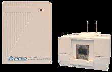
This is a battery operated Arduino project that uses the CM17A to wirelessly transmit the temperature to the power line. From there, it is picked up by the X10 Book, (see below) and displayed and logged. (It can also be used to trigger macros.)

The PSC05/TW523 will not receive X10 "extended" codes. Therefore I had to get tricky with how I sent the temperature and how I received it. This means that the technique requires you to have control over the receiving end as well.

The idea is simple. An entire House Code is dedicated to the temperature. Each digit is sent as a Unit Code representing that digit (i.e. Unit Code"3" is sent if the digit is 3). The Command is used to indicate the digit position. So for the least significant digit, I used "OFF" for the next digit I used "ON". BRIGHT and DIM can also be used for more positions or to represent + and -. So with 4 types of commands (and 4 separate transmissions) you can transmit variables up to "9999" or "+/-999".

[detail . . .]
Since Unit Codes really have a range of 1-16 you could use this to transmit even larger values - with 2 transmissions you could transmit and digit up to 255. However I choose not to do this because the CM17A is transmitting to the same (TM751) receiver that I use to receive form a motion sensor. The motion sensor uses Unit Codes 1 and 2. So in actuality I offset the digits by 5, leaving the first 5 Unit Codes. (Two for the motion sensor and 3 reserved.) I'm sure there are other methods you can use to transmit values, but this works fine for me.

So much for theory!
Since the CM17A is wireless, it's a nice idea to make the whole thing battery operated. There are techniques to use with the Arduino to conserve battery power. I used one that combines "sleep" mode with the "watchdog timer" There is a good example of this here. The idea is to have the Arduino in low power sleep mode, wake it up every now and then, and have it read and transmit the temperature before going back to sleep. The example cited has a maximum sleep time only 8 seconds, but on waking, a variable can simply be incremented and skip sending until say 10 wakeups have occurred. Mine sends the temperature about every 2 min. (The less often you send, the longer your battery lasts.)

I used the DS1621 temperature sensor. It's I2C and simple to connect. You will find examples of how to use it on the Arduino Forum.
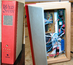
I put everything in a waterproof box. A word about the picture. You can see the DS1621 temperature sensor on the "spring" ribbon cable. The green square on the right is the CM17A with it's jackets removed and covered with heat shrink tubing. The Arduino (ATmemg128) board is a custom board I made that includes a boost circuit so it only needs 2 AA batteries. You can use any Arduino and use 3 AA batteries instead.

On the temperature receiver side (the X10 Book in my case) I look for commands from the dedicated temperature House Code. When I get one, I determine which digit position it represents by the command code, convert the Unit Code into a digit, and store it in a global for that digit position. It's OK if a digit is somehow missed, it's likely to be picked up from the next transmission. When I want to log or display the temperature (periodically or using the TV Remote) I simply multiply the values in the various digit positions to get the current temperature.

Here's a short video . . .

Thursday, May 21, 2009

The X10 Book

The X10 Book is the must useful project I've made with the Arduino. Again, I've already posted a lot of details on this elsewhere, so here I'll write about it from a different perspective (I hope).

The project is based on the Arduino interface to the PSC05/TW523 (see below) and an experiment on encasing electronic gizmos in a book.

It provides me with all the X10 functionality I had with with ActiveHome and a lot more. (I now use my CM15A only as a whole house transceiver.)

At the risk of repeating myself, for those who haven't read the links, here is a partial list of what it does:
  • Displays each X10 command that comes across the power line on a scrolling display. If it's a "known" house / unit code, it displays a friendly name like "Basement Light - On".
  • Stores a list of timed events like "turn on this light at 8PM, off at 10PM, on again at 11PM, etc.".
  • Checks X10 commands on the line, and trigger a "macro" if required - i.e "if garage Door open more than 10 min. display a warning, and trigger the sounder".
  • For defined X10 commands, light an LED and/or open or close a (10A) relay.
  • For selected commands, log the command and the time to an SD memory card that can be pulled and read by a PC.
  • Accept "special" X10 commands that provide variable data, such as temperature, from another X10 project I created (see next post). Note, these are not X10 "extended" commands.
So your saying "that's cool, good for you, but what about me?". Here is where I hope to be able to help by explaining the build process and offering a few tips. Since it's likely I don't know you, I'll imagine someone who is interested in X10, but has little or no experience with Arduino, some electronics, and an interest in programming. You are also patient, and motivated to help yourself. (Yuck, this is going to be long!)

The key things to remember, are that you don't have build all this functionality, you don't have to build it all at once, and you can build other functionality. You also don't have to build it the same way. For example you can use an LCD display instead of a scrolling LED matrix - much easier. If you use an LED matrix, there are several ways to drive it (i.e. MAX7221 vs "595's").

Another suggestion is to make the project in steps. Learn about and complete and test each step before going on to the next. This is where I think I can help the most. Below is the sequence of steps that I suggest you take to create an X10 controller with the Arduino.
  •  Get comfortable with the Arduino. Read the tutorials, join the forum, ask questions there, do some basic projects that interest you. (Get an Arduino with an ATmega328, you will need the room.)
  • Make a simple clock. I suggest a real time clock (RTC) based on the DS1307 chip. (IMO it's the simplest.)
  • For the clock, you will need a display. If you want a display on your controller, consider what you want there when considering your options. You have lots of options, but consider not biting off more that you can chew, you can always beef it up later. (i.e. A single color LED matrix is much simpler than a 2 color matrix.)
  • If you want a TV remote, figure out how to build that. I suggest a Sony protocol with a universal remote. For mine, I picked an interface that was interrupt driven rather than "blocking".
  • If you are going to display a lot of text, and to hold timed events, etc. get familiar with the I2C EEPROM.
  • This can be done earlier, but add the X10 stuff from here and here.
  • Recently, others have created some nice libraries that let you write to an SD card if you want a log.
  • Along the way, you have learned a great deal about electronics. Here is the schematic / wiring diagram for the X10 Book.
I'll add more to this list in future edits.


Sending and Receiving with the PSC05 / TW523


For a long time, the Arduino community had a library (written by Tom Igoe) that would interface the Arduino to the PSC05/TW523 so that it could send X10 commands. (available here) Since I was already wirelessly sending commands via the CM17A, I never took much interest in it.

But then I thought if you could also receive commands with the PSC05/TW523, you could pretty much make your own X10 controller and replace the ActiveHome SW and the CM11A/CM15A hardware.

Again the web provided a lot of the great detail on the protocol that enabled me to write an Arduino driver to receive commands with the PSC05/TW523. I created an example sketch and wrote a lot of background and posted it on the Arduino Playground here. Since the receive driver can coexist with the send library, the Arduino now has a complete interface with the PSC05/TW523 that allows you to send and receive X10 commands.


[3/30/2010] Thanks to Creatrope, a beta of the combined X10 send / receive library is now available - you'll find it here. [1/5/11] Creatrope site down. You can use the separate X10 transmit & receice libs or check out ThomasM's library here

The Playground article should tell you all you need to know about how to use this software, so I won't go into it here. Just to say that the Arduino is always looking for any X10 signal on the powerline at every zero crossing of the AC. When it gets one, it sets a flag, and fills out globals for the House Code, Unit Code, and Command that are used by your program.

With this complete, I was able to make my own X10 controller called the "X10 Book" that I will write about in my next post. 


Edit Nov. 2, 09: Based on a comment by Phil, here's a link to an Ap Note from Microchip that describes how to use a PIC to essentially replace the PSC05. It would be great to port it to ATmega chips. Thanks Phil!


Edit Feb. 23, 09: I've received some very good feedback from Johannes related to changing the send and receive software to have reliable communications using 50Hz line frequency. (He uses an "XM10" X10 module instead of the PSC05 / TW523 for 220V 50Hz.) It's simply a matter of changing 4 #defines - 2 in the X10.lib (for sending) and 2 in my code (for receiving).


In the source for your X10.lib, in X10constants.h change:
#define BIT_DELAY from 1778 to 2133
#define BIT_LENGTH from 800 to 900


In my example for the X10 Receive function, in PSC05.h change:
#define OFFSET_DELAY from 500 to 800
#define HALF_CYCLE_DELAY from 8334 to 10000


Thanks Johannes! I'm sure others will find this helpful.

Wednesday, May 20, 2009

The CM17A and Arduino

My first X10 project was to create an interface between the Arduino and the CM17A (aka "Firecracker"). The CM17A is a dongle that wirelessly (RF) sends X10 commands to X10 RF receivers. The receivers then send signals down the house wiring to control lights and appliances.

After many hours of Googling, I could not find any examples of an interface other than some written in assembler. However, I did find lots of good information about the protocol that is used to talk to the CM17A. With that I was able to write a small program ("sketch") that demonstrates how to have the Arduino talk to the CM17A. I wrote up an article with the explanation and example and posted it on the Arduino Playground here. It should tell you all you need to know.
I made a short video of a simple example where a TV remote is used to have the CM17A send X10 commands to a light.


Don't let the custom boards and led matrix scare you. There are much simpler ways to use the CM17A with Arduino. In a future post I will describe how it can be used to send the temperature to a home made X10 Controller.

What is Arduino? / What is X10?

It's likely that most people reading this will know a lot about either Arduino or X10. (If you know about both - you're in good shape. If you don't know about either - I'm surprised you're here!) In any case, I won't go into detail about either. You can learn about Arduino here, and Google will give you lots of info on X10.

In short, the Arduino is an inexpensive (~$30) microcomputer that you program in C/C++ that has input and output pins that connect to real world devices. I choose the Arduino because of it's popularity, price and wonderful support.  It's likely another type of microcomputer can be used for these projects, but I'm only comfortable discussing the Arduino and the C language.

X10 is a home automation system that typically sends signals down your power line to remotely control lights and appliances. There are many types of modules one can get to do various things. While X10 is old technology, it still has some key advantages regarding remote control. Primarily, it is the cheapest and safest way I know of to control things that plug into the power line. 

So what are the advantages when you combine the Arduino and X10? Here is a diagram where I tried to show X10 and Arduino working together.


From an X10 user's perspective, the X10 world now becomes your oyster. You are no longer bound by a PC and the limited functionality and cost of commercial software. You can create entirely new functionality while replacing your ActiveHome SW and your CM11A / CM15A interface device.

From an Arduino user's perspective, you gain an option for wireless remote control at a much lower cost per controlled device than say XBee and roll your own triacs. It's also a hell of a lot safer than mucking around with line voltage. The modules are UL approved and cost as little as $6 on Ebay  (link just an example).

Obviously, all of the above is just my opinion and points can be argued. You can fault X10 for not being reliable. Personally I solved most of my issues with a XPCR coupler /filter / amplifier. For those in 220V land, X10 charges an arm and a leg extra for the 200V models. See this website for a cheap way to convert most 115V modules.

OK, enough background.

Code Examples

In the posts above, I have provided links to the source I wrote for all examples.

If you are interested in example code for other areas of these projects, you can contact me at:
BroHoganX10@gmail.com

Well, here we go!

Much of what I post here, at least in the beginning, I have already posted in other locations. For example:
As I describe each project I'll include material from these links in addition to new material. As to how well I'll describe each project, that depends on you. Until I get questions, I won't go overboard. However, if I do get questions I will add the detail that covers them.

Welcome! - and I hope you find this interesting and helpful.

BroHogan (aka John)